Category Archives: Physics

Physics II: Chapter 6

ReferenceBeginning Physics II

Chapter 6: MAGNETISM-EFFECT OF THE FIELD

.

KEY WORD LIST

Magnetic Force, Magnetic Field, Circular Motion, Mass Spectrometer, Hall Effect, Semiconductor, Velocity Selector, Magnetic Torque, Magnetic Dipole Moment, Motor

.

GLOSSARY

For details on the following concepts, please consult Chapter 6.

MAGNETIC FIELD (B)
The magnetic field is a vector and is the link between the two moving charges that interact with each other. One of the charges is the source of the field, and this field, in turn, has the effect of exerting a force on the second moving charge. For magnetic field, we use the symbol B.

The unit for a magnetic field is a tesla (T) in our system. A more common unit which is widely used in practice is the gauss (G). One gauss equals 10-4 tesla. The strength of the magnetic field near the surface of the earth is approximately one gauss.

MAGNETIC FORCE (F)
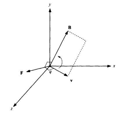
Experimentally we find that, in addition to the electrical force, there is also a force exerted by one moving charge on another moving charge. This force is the magnetic force. The formula for the magnitude of the force is:

Where the charge q is moving with velocity v when the angle between the vectors v and B is φ.

We have used absolute value signs, since the magnitude is always positive. The sign of q does not affect the magnitude of the force. It will, however, affect the direction of the force. Note that the force is zero when the velocity and the magnetic field are along the same line. Also, the largest force occurs when the velocity is perpendicular to the magnetic field.

The magnetic force for a current in the wire is:

The direction of the force is perpendicular to both v and B, and it is therefore necessary to consider the problem in three dimensions. The force points in the direction a right hand screw moves as it rotates from v to B.

CIRCULAR MOTION
A charged particle moving at constant speed at right angles to a magnetic field executes a circular motion in the plane perpendicular to B, because the force is always perpendicular to the direction of the motion. The magnitude of the magnetic force must equal the centripetal force required and we can therefore say that,

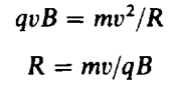
This is a formula for the radius of the circle traversed by the particle of mass, m, charge, q, moving with a velocity, v, in a perpendicular magnetic field, B.

SIGN OF THE CHARGE
If one has a charged particle of unknown sign, one can use the circular motion created by a magnetic field to determine the sign of the charge. It may also be used to determine the mass of a charged particle.

MASS SPECTROMETER
A mass spectrometer is an apparatus for separating isotopes, molecules, and molecular fragments according to mass. The sample is vaporized and ionized, and the ions are accelerated in an electric field and deflected by a magnetic field into a curved trajectory that gives a distinctive mass spectrum.

HALL EFFECT
Hall Effect is the production of a potential difference across an electrical conductor when a magnetic field is applied in a direction perpendicular to that of the flow of current.

SEMICONDUCTOR
A semiconductor is a material which has an electrical conductivity value falling between that of a conductor, such as copper, and an insulator, such as glass. A semiconductor’s resistivity falls as its temperature rises, in contrast to normal conductors (i.e. metals) whose resistivity rises with temperature.

VELOCITY SELECTOR
By using a combination of both electric and magnetic fields, we can produce a mechanism to separate out particles of a particular velocity. This is known as a velocity selector.

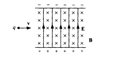
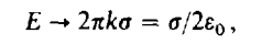
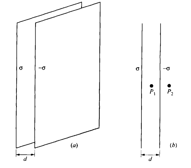
When the electric force is equal and opposite to the magnetic force, E = vB, or v = E/B. For a velocity of v = E/B there is no force to deflect the particle, and it will travel in a straight line. We can choose the velocity we want by varying E, simply by changing the potential difference across the two plates, which is producing the electric field.

MAGNETIC TORQUE
It is useful to define a vector area for the coil, A, whose magnitude is A = ab, and whose direction is perpendicular to the plane of the coil. The ±direction of A is determined by the right-hand rule. Curl the fingers of your right-hand around the coil in the direction of the current. Your thumb then points in the positive A direction. Thus φ is the angle between A (area vector) and B (magnetic field), as can be seen below. We see that in general the torque is given by

where Γ tends to rotate the coil in the same direction as rotating the vector A through φ to B. When A is parallel to B, φ = 0 and the torque is zero.

MAGNETIC DIPOLE MOMENT
We define a new vector, M, the magnetic dipole moment of the coil, whose magnitude is IA and whose direction is the same as A. If the coil consists of several turns, then each turn has a magnetic moment IA, and the entire coil has a magnetic moment NIA, where N is the number of turns in the coil. The torque will turn the coil in the direction of making M point in the direction of B.

Although this result was derived for the special case of a rectangle, the result is valid for any coil shape, with the moment of the coil equaling M = NIA, and the torque on the coil equaling MB sin φ, with the usual counter-clockwise, clockwise conventions.
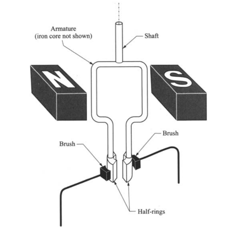
MOTOR
This phenomenon of a torque on a coil can be used to build a motor, which will continuously rotate in the magnetic field. Such motors are built by constructing a coil from many turns (to increase M and thereby, the torque), and suspending the coil on an axis in a constant magnetic field. The direction of the current in the coil is chosen to make the coil rotate in one particular direction, for instance clockwise. When the coil passes the y axis the direction of the torque would normally reverse, making the coil turn counter-clockwise. In order to prevent this from happening, we arrange to have the current direction reverse as the coil passes through the y axis, thus maintaining a clockwise torque. This is accomplished by the split in the rings where the current enters from the source of EMF.

.

Physics II: Chapter 5

ReferenceBeginning Physics II

Chapter 5: SIMPLE ELECTRIC CIRCUITS

.

KEY WORD LIST

EMF, Current, Resistance, Resistivity, Current Density, Ohm’s Law, Drift Velocity, Resistors in Series, Resistors in Parallel, Fuse, Terminals, Anode, Cathode, Open Circuit EMF, Internal Resistance, Discharge, Recharge, Work (Recharge), Ammeter, Voltmeter, Null Measurement, Wheatstone Bridge, Power

.

GLOSSARY

For details on the following concepts, please consult Chapter 5.

EMF (V)
The energy per unit charge supplied by the external source in maintaining the voltage is called the EMF (“electromotive force”-although it is not a force, but the name has stuck for historical reasons), and it is the EMF that replenishes the electrical energy lost as the charges flow within the conductor. In a steady state situation the external energy supplied per unit charge returned to the front end of the conductor exactly equals the electrical energy per unit charge expended in moving a unit charge through the conductor (from front to back). Hence the EMF equals the voltage across the conductor. EMF is measured in volts.

CURRENT (I)
The amount of charge that flows through the wire per second is called the current. The symbol we use for current is I, and the unit is ampere (one ampere is one coulomb/s).By our convention, the direction of the current is the direction of flow of positive charge. This means that the current always flows from high to low potential. Mathematically, the current is defined as

I = ∆q/∆t

where ∆q is the effective positive charge passing a cross-section of the conducting wire in the time ∆t, and the direction of I is the direction of flow of positive charge.

RESISTANCE (R)
We define a quantity called the resistance of the wire, R, as the ratio of voltage across the wire to the current flowing through the wire, R = V/I. The wire itself is called a resistor. The unit for R is V/A which we call an ohm (Ω). For most ordinary conducting materials and for ordinary currents, R is very nearly a constant. The Ohm’s law states that the current is directly proportional to the voltage, with R as the constant of proportionality:

V = IR

RESISTIVITY (ρ)
The resistance R is inversely proportional to the area A; and directly proportional to the length d. Therefore,

R = ρd/A,

where the constant of proportionality ρ is called the resistivity of the material. The resistivity ρ depends on the material being used and has the dimensions of Q – m. Materials that conduct electricity very easily have low resistivities and materials that resist the flow of current have high resistivities. The inverse of resistivity is called conductivity.

CURRENT DENSITY (J)
We define the current density J as the current/unit cross-section area so:

J = I/A

OHM’S LAW
Ohm’s law states that the current through a conductor between two points is directly proportional to the voltage across the two points. Introducing the constant of proportionality, the resistance, one arrives at the following mathematical relationship:

I = V/R

where I is the current through the conductor, V is the voltage measured across the conductor and R is the resistance of the conductor. A more basic form of Ohm’s Law is,

J = σE

Where J is the current density, and E is the electric field. The constant of proportionality σ is called conductivity, which is inverse of resistivity ρ.

DRIFT VELOCITY (vD)
The drift velocity is the average velocity attained by charged particles, such as electrons, in a material due to an electric field.

vD = I/neA

Where, I is the current flow, n is free electron density, e is charge of an electron, and A is the cross sectional area

RESISTORS IN SERIES
When resistors are connected in series as follows, the current flowing through each resistor is the same. For resistors in series.

RESISTORS IN PARALLEL
When resistors are connected in parallel, each branch has the same potential difference or voltage. For resistors in parallel,

FUSE
A fuse is a device which has very low resistance, and is made of material that will melt (i.e. burn out) when the current gets too high. The fuse burns out before other wires or resistors burn out or get so hot that nearby objects catch fire. When the fuse burns out all current ceases in the series circuit.

TERMINALS
Any source of EMF is a device in which positive and negative charges are separated. The two ends of such a device are called terminals. On one terminal positive charge will accumulate and on the other terminal negative charge will accumulate.

ANODE
The positively charged terminal is called the anode.

CATHODE
The negatively charged terminal is called the cathode.

OPEN CIRCUIT EMF
Open circuit EMF is the potential difference established between the terminals when no current flows because no wire has been connected between the terminals.

INTERNAL RESISTANCE
The open circuit EMF reduces by some amount when the circuit is closed and there is a current. To a good approximation, this reduction is proportional to the current, so EMF = V – Ir, where r is the proportionality constant. As can be seen; r has the same dimensions as resistance and is called the “internal resistance”, Rint, of the source, and treated like any other resistance.

DISCHARGE
A battery “discharging” means that the energy stored in the battery is reduced whenever the battery supplies current to an external circuit.

RECHARGE
In recharging a battery, energy must be delivered to the chemicals within the battery and be stored in the form of chemical energy of the molecules of the medium. To accomplish this one uses a different source of EMF, such as a generator, and applies a voltage across the terminals of the battery from this external source which will try to force current to flow in the desired direction. If the EMF of the external source is greater than the EMF of the battery, then current will flow in the direction determined by the external source. In that case the battery will receive energy and, if the battery is of the type that can be recharged, that energy will be stored in the battery.

WORK (RECHARGE)
The work done in moving a charge q through an EMF, ℇ, is qℇ.

AMMETER
An ammeter is an instrument that measures current. To measure the current in a circuit, it is obvious that one must place the ammeter in series within the circuit so that the same current flows in the meter as in the circuit. It would seem that the current read on the meter will then equal the current in the circuit. In order to minimize the effect of the ammeter on the current we must build our meters to have a very small resistance compared with the resistance R in the circuit we are measuring. Thus ammeters must always have small resistances to be accurate in their measurements.

VOLTMETER
A voltmeter is an instrument that measures voltage. A voltmeter must be connected in parallel with the circuit element whose voltage we seek. In order to minimize the change, we require that very little current be diverted through the voltmeter. This can be accomplished by making the resistance of the voltmeter very large compared to R. If this is not the case, one has to correct the reading to account for the effect of the voltmeter.

NULL MEASUREMENT
It is clear that the ideal way to measure a resistance is to use meters that do not draw any current when they are in the circuit. This would be a case of a null measurement where the result depends on adjusting a dial until the meter reads zero. The corresponding instrument that is used to measure resistance using a null method is the Wheatstone bridge.

WHEATSTONE BRIDGE
In the circuit for the Wheatstone bridge shown below, the unknown resistor is X, and the other resistors M, N and P are known. When the EMF is applied to the circuit, the known resistors are adjusted so that no current flows through the galvanometer G, between points b and c. Then no adjustments are necessary for the resistance of the galvanometer. The unknown resistance X may then be determined in terms of known resistors M, N and P.

POWER
Power is the rate at which energy is dissipated in the external circuit. This power is available for work (turning a motor) or for heat (in an electric heater or light bulb). The electrical energy that a charged particle loses is qV. That rate at which the energy is lost, the power, equals

P = ∆(qV)/∆t = V(∆q/∆t) = VI

If we have a potential difference V across a resistance R, then V = IR and

P = IV = I(IR) = I2R = V2/R

.

Physics II: Chapter 4

ReferenceBeginning Physics II

Chapter 4: ELECTRIC POTENTIAL AND CAPACITANCE

.

KEY WORD LIST

Conservative Force, Electric Potential Energy, Electric Potential, Equipotential Surface, Electron-Volt, Capacitance, Capacitor, Parallel Capacitors, Series Capacitors, Energy Of Capacitors, Dielectric, Polarize, Dipoles, Dielectric Constant, Permittivity

.

GLOSSARY

For details on the following concepts, please consult Chapter 4.

CONSERVATIVE FORCE (Newton)
Forces, in general, are able to do work, and the work that they do can be transformed into kinetic energy. For forces that are “conservative” the work done can be expressed in terms of a change in potential energy associated with those forces. In other words, the total work done in moving a particle between two points is independent of the path taken. Equivalently, if a particle travels in a closed loop, the total work done by a conservative force is zero.

ELECTRIC POTENTIAL ENERGY (Joules)
The electric force is conservative, and work can be written in the form of a change in potential energy. The potential energy of two charges q and Q separated by a distance r is then given by:

The zero of potential energy has been chosen when r → ∞. If the charges are of the same sign, then the potential energy increases as the charges approach each other. This follows because an external force must do positive work in forcing the charges closer together against their mutual repulsion. If left to themselves, these charges would seek regions of lower potential energy.

ELECTRIC POTENTIAL (Volt = Joules/coulomb)
We could associate a specific potential energy with each point in space in a manner similar to associating an electric field to each point in space. We can view this as a situation in which the stationary charges provide each point in space with a scalar value, called the potential, V, such that the potential energy of the system will equal qV if the moving charge is at that point in space.

The unit for potential is joules per coulomb, which is the same as volt (V). The quantity ∆V is the “potential difference” between two points in the static electric field. It corresponds to the work needed per unit of charge to move a test charge between the two points. The potential is related to the potential energy in the same manner that the electric field is related to the electric force.

Voltage = Energy / charge

The relationship of electric potential to electric field is as follows:

Potential always decreases as we move along the direction in which the field points.

EQUIPOTENTIAL SURFACE
At every point there is an electric field pointing in some direction. If we move to a different point along that direction, then the potential will change. However, if we move to a different point perpendicular to that direction, the potential will not change. If we move from point to point, always in a direction perpendicular to the electric field at that point, we will sweep out a surface with all points on that surface at the same potential. This surface is called the “equipotential surface”.

A knowledge of how V varies in a region around a point allows us to obtain the magnitude and the direction of the electric field at that point.

E = -∆V/∆d

The minus sign means that E points from high to low potential.

ELECTRON-VOLT
The potential energy of any charge is given by qV, and the change in potential energy that is used in most energy related problems is ∆Up = q ∆V. A positive charge gains energy as it moves to a region of higher potential. A negative charge, such as an electron, will lose energy as it moves to a higher potential. When an electron moves through a difference of potential of one volt it gains or loses e(1) = 1.6 x 10⁻¹⁹ J of energy. This amount of energy is called an electron-volt, or eV. This is a very convenient unit of energy to use whenever one discusses the motion of an electron.

CAPACITANCE
Let us consider the case of two isolated conductors with charge +Q on one and -Q on the other, and a potential difference V between them. Depending on the shape of the conductors and their positions relative to each other, the charges on the conducting surfaces will distribute themselves with some definite (but not necessarily uniform) charge distribution. It is not hard to see that the potential difference V is proportional to the charge Q, as long as the geometry stays the same. We can therefore write Q = CV, and the constant C is called the capacitance of the system. This constant C = Q/V depends on the geometry of the conductors, their size, shape and position, but it does not depend on the charge on the plates. The unit for capacitance is the farad (F).

CAPACITOR
If we build a unit containing two conductors with relatively large surfaces close to each other (but not touching) we call this object a capacitor whose capacitance is C. The name derives from the fact that C represents the capacity of the two conductors to store charge on their surfaces per unit potential difference (per volt) between them. A large capacitance means that the capacitor holds a lot of charge per volt. The most common capacitor geometry is that of two close parallel, conducting plates.

The capacity of a parallel plate capacitor can be written as C = ε0A/d. Thus, doubling the area, or halving the distance between the plates, doubles C as well.

A capacitor has the property that there is no current flow through it, so that, in the steady state it acts like an open circuit. However, the capacitor can become charged as a result of current flowing towards its positive plate, and discharged as a result of charge flowing away from its positive plate. Therefore, current can flow in a DC circuit containing a capacitor, during the time that the capacitor is charging or discharging.

PARALLEL CAPACITORS
When capacitors are connected in parallel as follows, each branch has the same potential difference or voltage. For two parallel capacitors,

SERIES CAPACITORS
When capacitors are connected in series as follows, the potentials V1 and V2 across the capacitors need not be the same.  Indeed, the total voltage between a and b is V = V1 + V2. If we examine the figure more closely, we note that each capacitor will have the same charge. For two series capacitors,

ENERGY OF CAPACITORS
If a capacitor is charged to a difference of potential V, then the energy stored in a capacitor can be written as

The energy that is stored in a capacitor can be viewed as the energy stored in these electric fields. The entry density within the capacitor may be expressed as,

DIELECTRICS
A dielectric is a medium or substance that transmits electric force without conduction. Normal insulating materials are dielectrics. They consist of atoms and molecules that are composed of positively charged nuclei and negatively charged electrons that are tightly bound together with no loose outer electrons that are free to roam. In the presence of an electric field the positive and negative charges in the atoms and molecules are pulled in opposite directions. As a result, the atoms and molecules will become somewhat “polarized” with the positive and negative charges becoming slightly separated from their equilibrium positions. We will then have tiny “dipoles” throughout the material. [See the beginning sketch above.]

POLARIZE
See DIELECTRICS.

DIPOLES
See DIELECTRICS.

DIELECTRIC CONSTANT
If the polarization is proportional to the field, then the new total field will be proportional to the field that would be produced in the absence of the dielectric material. We can then write that E = E0/κ, where E is the total field in the presence of the dielectric, E0 is the field that would be present without the dielectric and κ is the “dielectric constant” of the material. These dielectric constants vary from material to material.

PERMITTIVITY
Permittivity (ε) is a measure of the electric polarizability of a dielectric. A material with high permittivity polarizes more in response to an applied electric field than a material with low permittivity, thereby storing more energy in the material. In electrostatics, the permittivity plays an important role in determining the capacitance of a capacitor. ε0 is called the permittivity of free space. ε = κε0 is called the “permittivity” of the material.

.

Mathematical Results

.

Physics II: Chapter 3

Reference: Beginning Physics II

Chapter 3: COULOMB’S LAW AND ELECTRIC FIELDS

.

KEY WORD LIST

Electric Charge, Electric Force, Law Of Conservation Of Charge, Conductors, Ground, Coulomb’s Law, Electric Field, Electric Field Lines, Flux Density, Flux, Flux Density, Gauss’ Law (for Electric Field), Gaussian Surface

.

GLOSSARY

For details on the following concepts, please consult Chapter 3.

ELECTRIC CHARGE
Electric charge is created when amber rod is rubbed with fur. By convention, the charge on amber rod is considered positive and that on the fur is considered negative. In ordinary matter, negative charge is carried by electrons, and positive charge is carried by the protons in the nuclei of atoms. Atoms are neutral because the number of electrons surrounding the nucleus equals the number of protons in the nucleus.  A point charge that is static requires a material base to exist on, which is usually an atom or a molecule. The negative charge is the material base with an additional electron. The positive charge is a material base lacking an electron. Charge is measured in units of Coulomb (C). The magnitude of the charge of an electron (e) is 1.602 x 10⁻¹⁹ C.

ELECTRIC FORCE
All charged particles exert a force on each other called the electric force. When one separates the charges one can explore the force between them. It is found that the force is one of attraction between charges of opposite polarity and of repulsion between charges of like polarity. Furthermore, the magnitude of the force decreases as the charges move further apart.

LAW OF CONSERVATION OF CHARGE
This law requires that the total amount of charge remains unchanged. If one starts with uncharged materials the initial charge present is zero. Then the total charge after it has been separated must still add to zero, requiring that there be equal amounts of positive and negative charge present.

CONDUCTORS
In many materials, called conductors, there are some charges, usually electrons in the outer reaches of the atoms, which are free to move in the material. If the conducting material is uncharged, then the electrons are uniformly distributed in the material, with each electron being attracted to a fixed, positively charged nucleus. If other charges are inserted in the conductor, then the free charges move in response to the electrical forces that occur. Since it is the electrons that move, a piece of conductor can be given a negative charge by adding some electrons from elsewhere, or a positive charge by removing some electrons to another location. This charge is found distributed on the surface of the conductor because similar charges repels each and they end up on the surface where the area is maximum to spread out on. The interior of the conductor remains neutral. when a charged conductor is brought close to a neutral conductor, it creates an opposite charge on the surface of the second conductor.

GROUND
The ground is a large uncharged reservoir.

COULOMB’S LAW
Coulomb’s law is the quantitative law which gives the force between two charged particles. It states that the magnitude of the electrostatic force of attraction or repulsion between two point charges is directly proportional to the product of the magnitudes of charges and inversely proportional to the square of the distance between them.

Here, ke is the Coulomb constant (ke ≈ 8.988 × 10⁹ N⋅m2⋅C−2), q1 and q2 are the assigned magnitudes of the charges, and the scalar r is the distance between the charges.

The direction of the force is along the line joining the charges. If the charges are of the same sign, then the force is one of repulsion, i.e. it is directed away from q1, while if the charges are of opposite sign then the force is one of attraction, i.e. it is directed toward q1. Of course, there will also be a force exerted by q2 on q1, which will have the same magnitude as the force on q2 but will be in the opposite direction.

NOTE: Like the gravitational force, the electric force is also looked upon as “action at a distance.” The formula for the magnitude of the force is identical in form to that for the gravitational force between two masses. On an atomic and molecular scale, gravitational forces are negligible compared to electrical forces and can almost invariably be neglected.

ELECTRIC FIELD
An electric field is the physical field that surrounds electrically charged particles and exerts force on all other charged particles in the field, either attracting or repelling them. It also refers to the physical field for a system of charged particles. The electric field is defined as a vector field that associates to each point in space the electrostatic (Coulomb) force per unit of charge exerted on an infinitesimal positive test charge at rest at that point. The derived SI unit for the electric field is the newton per coulomb (N/C).

Suppose one has an electric field E at a certain position in space. If we now place a charge Q at that point the electric field will exert a force on the charge, given by:

F = QE

ELECTRIC FIELD LINES
A field line is a graphical visual aid for visualizing vector fields. These are lines traced through space in such a way that as the line passes through a point it always aims in the direction of the electric field at that point. One can always determine the direction of the electric field at a point in space by drawing the tangent to the electric field line going through that point. All the lines begin on positive charges and end on negative charges. It cannot happen that lines cross each other since at the point of crossing there would then be two directions for the electric field, which cannot happen.

FLUX (F)
Flux is the number of field lines passing through any given area. The field produced by the charge q has a magnitude of (1/4πε0) q/r2. Equating this to the number of field lines per unit area, we get N/4πr2 = q/4 πε0 r2, or N = q/ε0.

Choosing N, the representative number of field lines drawn from the charge q, to equal q/ε0 is particularly useful because we can now deduce the magnitude of the electric field at any point P at any distance R from the charge in terms of the lines/area at that point. The lines/area at a point P is defined as the number of lines passing through a small “window” centered on the point P and facing perpendicular to the field lines, divided by the small area of the window.

The lines/area (as defined above) when chosen to equal |E|, is called the flux density, and the number of lines passing through any given area is called the flux through that area. Flux is positive when its direction is the same as the area vector.

Note: Thinking in terms of lines/area is a very useful pictorial device for understanding the behavior of the electric field, but ultimately all the results we obtain are expressible directly in terms of the electric field E and do not depend on the artifact of lines that are drawn through space.

Noting that E cos θ is just the component of E parallel to A (area vector), we see that the flux through A is just the component of E along A times the magnitude of A:

Flux = E (cos θ) A

This is an equivalent definition of flux that needs no reference to “field lines per unit area” or other intuitive constructs.

GAUSS’ LAW (ELECTRIC FIELD)
For a closed surface, if the flux is positive then net flux leaves the surface, i.e. more lines leave the surface than enter the surface. If the sum is negative, then on net more lines have entered the surface from outside than leave. The net electric flux through any hypothetical closed surface is equal to 1/ε0 times the net electric charge enclosed within that closed surface.

where E is the total electric field due to all charges in the universe and Qin is the total charge enclosed in the surface. The closed surface is also referred to as Gaussian surface.

.

Mathematical Results

See the chapter for problems and their solutions.

(1) The electric field produced by the charge on the ring:

The field at the center of the ring (P1) will be zero. The field at point P2 will be:

.

(2) The electric field produced by the charge distributed uniformly on a sphere:

The magnitude of the field outside the sphere is given by E = kQ/r2, where Q is the total charge on the sphere. This is the same field that would be produced by a point charge Q located at the center of the sphere.

.

(2) The electric field produced by the charge distributed uniformly on a disk:

The field at point P will be:

When one is close to the disk or “far” from the edge from planar planar charge distribution of any shape (i.e. x << R):

.

(3) The electric field produced by the charge distributed uniformly on a rod:

The field at point P will be:

where Q = 2Lλ is the total charge on the rod.

.

(4) The electric field produced by two oppositely charged parallel plates, where the distance between them is much smaller than the linear dimension of the charged area:

At point P1, both fields point toward the right, and the total field is therefore,

At point P2, the fields point in opposite directions, and the total field is therefore zero.

.

Inertia, Gravity and Charge

Dimensions

  1. Cycles – T-1, Time – T,  Distance – L
  2. Speed – LT-1, Momentum – MLT-1
  3. Acceleration – LT-2, Force – MLT-2
  4. Energy – ML2T-2

,

Motion and Inertia

  1. Oscillation has period (T) and frequency (T-1). Frequency is inverse of period. 
  2. Motion adds wavelength to oscillation (LT-1). Inertia comes about as motion increases ((M = L-1T). Inertia is inverse of motion.
  3. Mass (inertia) is essentially inverse of motion. Momentum, therefore, has no unit. Momentum is naturally conserved.
  4. Motion decreases as mass increases. Motion and mass balance each other.

.

Space and Gravity

  1. Motion manifests as the size of the particle. Inertia manifests as the centeredness of the particle.
  2. Thus, particle of substance has the properties of size and centeredness.
  3. There is a spectrum of substance from space to field to matter.
  4. Space (gravitational field) is condensing into mass on a gradient, as its motion is slowing down.
  5. Gravity is the medium inside the particle that carries force.
  6. An accelerating body is at “rest” in a gravitational field. Gravity is inverse of acceleration.

.

Force and Substance

  1. Total momentum of an isolated system remains unchanged in spite of interactions within it.
  2. Force is manifested with change in momentum. Since momentum is conserved there is equal and opposite reaction.
  3. Such reaction is the basis of all sensation. Sensation is the basis of substance. It is awareness.
  4. The dimensions of force (MLT-2) reduce to the dimension of frequency (T-1) when mass is seen as inverse of motion.
  5. Thus, the core of centeredness is frequency. This is fixation of attention.

.

Charge

  1. A sudden change in gravitational force manifests as charge. This is felt as shock.
  2. Charge manifests at the interface between the nucleus and the electronic region of the atom.

.