

Reference: Beginning Physics II
Chapter 5: SIMPLE ELECTRIC CIRCUITS
.
KEY WORD LIST
EMF, Current, Resistance, Resistivity, Current Density, Ohm’s Law, Drift Velocity, Resistors in Series, Resistors in Parallel, Fuse, Terminals, Anode, Cathode, Open Circuit EMF, Internal Resistance, Discharge, Recharge, Work (Recharge), Ammeter, Voltmeter, Null Measurement, Wheatstone Bridge, Power
.
GLOSSARY
For details on the following concepts, please consult Chapter 5.
EMF (V)
The energy per unit charge supplied by the external source in maintaining the voltage is called the EMF (“electromotive force”-although it is not a force, but the name has stuck for historical reasons), and it is the EMF that replenishes the electrical energy lost as the charges flow within the conductor. In a steady state situation the external energy supplied per unit charge returned to the front end of the conductor exactly equals the electrical energy per unit charge expended in moving a unit charge through the conductor (from front to back). Hence the EMF equals the voltage across the conductor. EMF is measured in volts.
CURRENT (I)
The amount of charge that flows through the wire per second is called the current. The symbol we use for current is I, and the unit is ampere (one ampere is one coulomb/s).By our convention, the direction of the current is the direction of flow of positive charge. This means that the current always flows from high to low potential. Mathematically, the current is defined as
I = ∆q/∆t
where ∆q is the effective positive charge passing a cross-section of the conducting wire in the time ∆t, and the direction of I is the direction of flow of positive charge.
RESISTANCE (R)
We define a quantity called the resistance of the wire, R, as the ratio of voltage across the wire to the current flowing through the wire, R = V/I. The wire itself is called a resistor. The unit for R is V/A which we call an ohm (Ω). For most ordinary conducting materials and for ordinary currents, R is very nearly a constant. The Ohm’s law states that the current is directly proportional to the voltage, with R as the constant of proportionality:
V = IR
RESISTIVITY (ρ)
The resistance R is inversely proportional to the area A; and directly proportional to the length d. Therefore,
R = ρd/A,
where the constant of proportionality ρ is called the resistivity of the material. The resistivity ρ depends on the material being used and has the dimensions of Q – m. Materials that conduct electricity very easily have low resistivities and materials that resist the flow of current have high resistivities. The inverse of resistivity is called conductivity.
CURRENT DENSITY (J)
We define the current density J as the current/unit cross-section area so:
J = I/A
OHM’S LAW
Ohm’s law states that the current through a conductor between two points is directly proportional to the voltage across the two points. Introducing the constant of proportionality, the resistance, one arrives at the following mathematical relationship:
I = V/R
where I is the current through the conductor, V is the voltage measured across the conductor and R is the resistance of the conductor. A more basic form of Ohm’s Law is,
J = σE
Where J is the current density, and E is the electric field. The constant of proportionality σ is called conductivity, which is inverse of resistivity ρ.
DRIFT VELOCITY (vD)
The drift velocity is the average velocity attained by charged particles, such as electrons, in a material due to an electric field.
vD = I/neA
Where, I is the current flow, n is free electron density, e is charge of an electron, and A is the cross sectional area
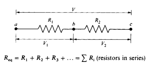
RESISTORS IN SERIES
When resistors are connected in series as follows, the current flowing through each resistor is the same. For resistors in series.
RESISTORS IN PARALLEL
When resistors are connected in parallel, each branch has the same potential difference or voltage. For resistors in parallel,

FUSE
A fuse is a device which has very low resistance, and is made of material that will melt (i.e. burn out) when the current gets too high. The fuse burns out before other wires or resistors burn out or get so hot that nearby objects catch fire. When the fuse burns out all current ceases in the series circuit.
TERMINALS
Any source of EMF is a device in which positive and negative charges are separated. The two ends of such a device are called terminals. On one terminal positive charge will accumulate and on the other terminal negative charge will accumulate.
ANODE
The positively charged terminal is called the anode.
CATHODE
The negatively charged terminal is called the cathode.
OPEN CIRCUIT EMF
Open circuit EMF is the potential difference established between the terminals when no current flows because no wire has been connected between the terminals.
INTERNAL RESISTANCE
The open circuit EMF reduces by some amount when the circuit is closed and there is a current. To a good approximation, this reduction is proportional to the current, so EMF = V – Ir, where r is the proportionality constant. As can be seen; r has the same dimensions as resistance and is called the “internal resistance”, Rint, of the source, and treated like any other resistance.
DISCHARGE
A battery “discharging” means that the energy stored in the battery is reduced whenever the battery supplies current to an external circuit.
RECHARGE
In recharging a battery, energy must be delivered to the chemicals within the battery and be stored in the form of chemical energy of the molecules of the medium. To accomplish this one uses a different source of EMF, such as a generator, and applies a voltage across the terminals of the battery from this external source which will try to force current to flow in the desired direction. If the EMF of the external source is greater than the EMF of the battery, then current will flow in the direction determined by the external source. In that case the battery will receive energy and, if the battery is of the type that can be recharged, that energy will be stored in the battery.
WORK (RECHARGE)
The work done in moving a charge q through an EMF, ℇ, is qℇ.
AMMETER
An ammeter is an instrument that measures current. To measure the current in a circuit, it is obvious that one must place the ammeter in series within the circuit so that the same current flows in the meter as in the circuit. It would seem that the current read on the meter will then equal the current in the circuit. In order to minimize the effect of the ammeter on the current we must build our meters to have a very small resistance compared with the resistance R in the circuit we are measuring. Thus ammeters must always have small resistances to be accurate in their measurements.
VOLTMETER
A voltmeter is an instrument that measures voltage. A voltmeter must be connected in parallel with the circuit element whose voltage we seek. In order to minimize the change, we require that very little current be diverted through the voltmeter. This can be accomplished by making the resistance of the voltmeter very large compared to R. If this is not the case, one has to correct the reading to account for the effect of the voltmeter.
NULL MEASUREMENT
It is clear that the ideal way to measure a resistance is to use meters that do not draw any current when they are in the circuit. This would be a case of a null measurement where the result depends on adjusting a dial until the meter reads zero. The corresponding instrument that is used to measure resistance using a null method is the Wheatstone bridge.
WHEATSTONE BRIDGE
In the circuit for the Wheatstone bridge shown below, the unknown resistor is X, and the other resistors M, N and P are known. When the EMF is applied to the circuit, the known resistors are adjusted so that no current flows through the galvanometer G, between points b and c. Then no adjustments are necessary for the resistance of the galvanometer. The unknown resistance X may then be determined in terms of known resistors M, N and P.

POWER
Power is the rate at which energy is dissipated in the external circuit. This power is available for work (turning a motor) or for heat (in an electric heater or light bulb). The electrical energy that a charged particle loses is qV. That rate at which the energy is lost, the power, equals
P = ∆(qV)/∆t = V(∆q/∆t) = VI
If we have a potential difference V across a resistance R, then V = IR and
P = IV = I(IR) = I2R = V2/R
.
