Category Archives: Physics

Physics II: Chapter 15

Reference: Beginning Physics II

Chapter 15: INTERFERENCE. DIFFRACTION AND POLARIZATION

.

KEY WORD LIST

Phase, In Phase, Out of Phase, Interference, Constructive Interference, Destructive Interference, Interference versus Diffraction, Huygens’ Wavelets, Double Slit, Michelson Interferometer, Thin Film Interference, Non-Reflecting Coating, Wedge, Newton’s Rings, Diffraction, Single Slit, Single Hole, Diffraction Grating, Polarization Of Light, Absorption (Dichroism), Reflection, Birefringence, Scattering.

.

GLOSSARY

For details on the following concepts, please consult Chapter 15.

PHASE
Phase
is the fraction of a period that a point completes after last passing through the reference, or zero, position. Phase is the ratio of elapsed time t to the period T, or t/T—and is equal to the ratio of the phase angle to the angle of the complete cycle, 360°, or 2π radians.

IN PHASE
When comparing the phases of two or more periodic motions, such as waves, the motions are said to be in phase when corresponding points reach maximum or minimum displacements simultaneously. The actual displacement is given at any time by the sum of these two displacements, using the principle of superposition.

The two waves are in phase not only if they take the same time to reach the new point, but also if one of them takes exactly one period longer than the other (or any integral multiple of the period longer).

OUT OF PHASE
If the crest of one and the trough of the other pass at the same time, the phase angles differ by 180°, or π radians, and the waves are said to be out of phase.

Here the time delay is of half a period, ∆t = T/2, or any half integral multiple of T, ∆t =
(m+ ½)T
, between the two waves. The two waves are said to be “180° out of phase”, or “out of phase by π (radians)” or simply “out of phase.”

INTERFERENCE
Interference is the net effect of the combination of two or more waves moving on intersecting or coincident paths. The effect is that of the addition of the amplitudes of the individual waves at each point affected by more than one wave.

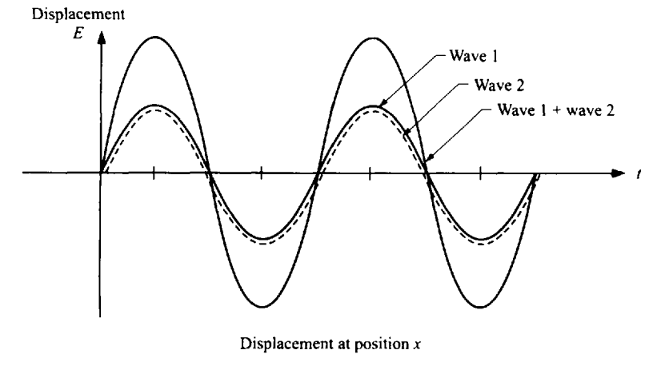
CONSTRUCTIVE INTERFERENCE
If two of the components are of the same frequency and phase, the wave amplitudes are reinforced, producing constructive interference.

∆t = mT           or         ∆l = mλ → constructive interference with m integer

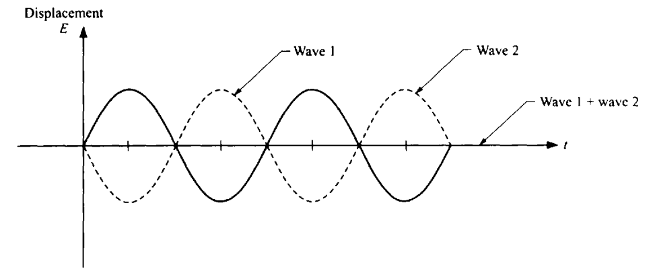
DESTRUCTIVE INTERFERENCE
If the two waves are out of phase by 1/2 period (i.e., one is minimum when the other is maximum), the result is destructive interference, producing complete annulment if they are of equal amplitude.

∆t = (m +½) T       or       ∆l = (m +½) λ → destructive interference with m integer

INTERFERENCE VERSUS DIFFRACTION
If we have more than two waves then we must add together all the waves to get the resultant wave. This will clearly result in a more complicated calculation in practice, although the underlying principle is still the same. Typically, when we consider waves traveling through openings in different barriers arriving at a common point, we use the term interference to characterize the results of their addition. This often involves the addition of a relatively small number of waves. If we add together waves coming from different parts of a single aperture and arriving at a common point, we usually refer to the effect as diffraction, and the addition can involve, in principle, large numbers of waves. Nonetheless, the basic principle for diffraction is the same as for interference.
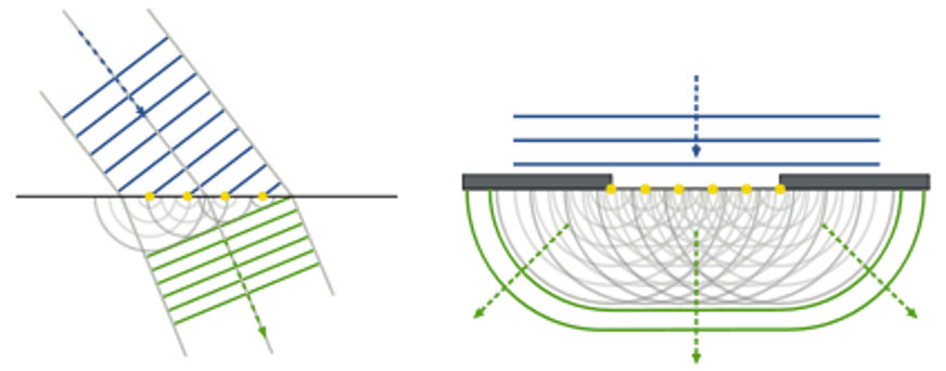
HUYGEN’S WAVELETS
The Huygens–Fresnel principle states that every point on a wavefront is itself the source of spherical wavelets, and the secondary wavelets emanating from different points mutually interfere. The sum of these spherical wavelets forms a new wavefront.

DOUBLE SLIT
The double slit is an example of interference. From the geometry, the following result can be derived mathematically.

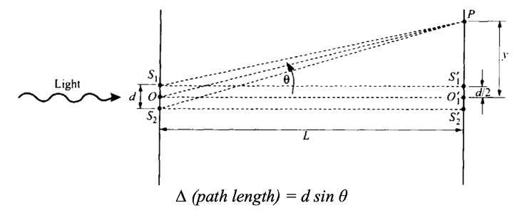
We can now determine the angles at which we have destructive and constructive interference by equating this difference in path length to the appropriate multiples of λ. The angle at which the first maximum occurs depends on λ/d. When λ/d is small, then sin θ is small, as is θ. If the ratio is not too small, one can see these interference effects. For wavelengths that are very short compared to the geometric dimensions of slits and apertures, there is little ability of the light to bend and there will be neither diffraction nor interference that is detectable. To see fringes, one needs this ratio to be much less than 1, but still not minuscule. One could use the double slit to measure the wavelength of some unknown radiation by measuring the angle at which interference occurs. In practice, one gets greater experimental accuracy if one uses a diffraction grating that contains thousands of slits rather than just two slits.

MICHELSON INTERFEROMETER
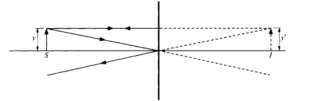
Here, light from a source, S, gets split and travels two different paths to reach the detector as shown.       The criterion for constructive interference remains that the difference in path length, 2∆D, equals an integral multiple of the wavelength.

As we change the distance to one of the mirrors, the detector will alternately record a large intensity and zero intensity as the interferometer changes from constructive to destructive interference and back again. This can be used to measure very small distances accurately.

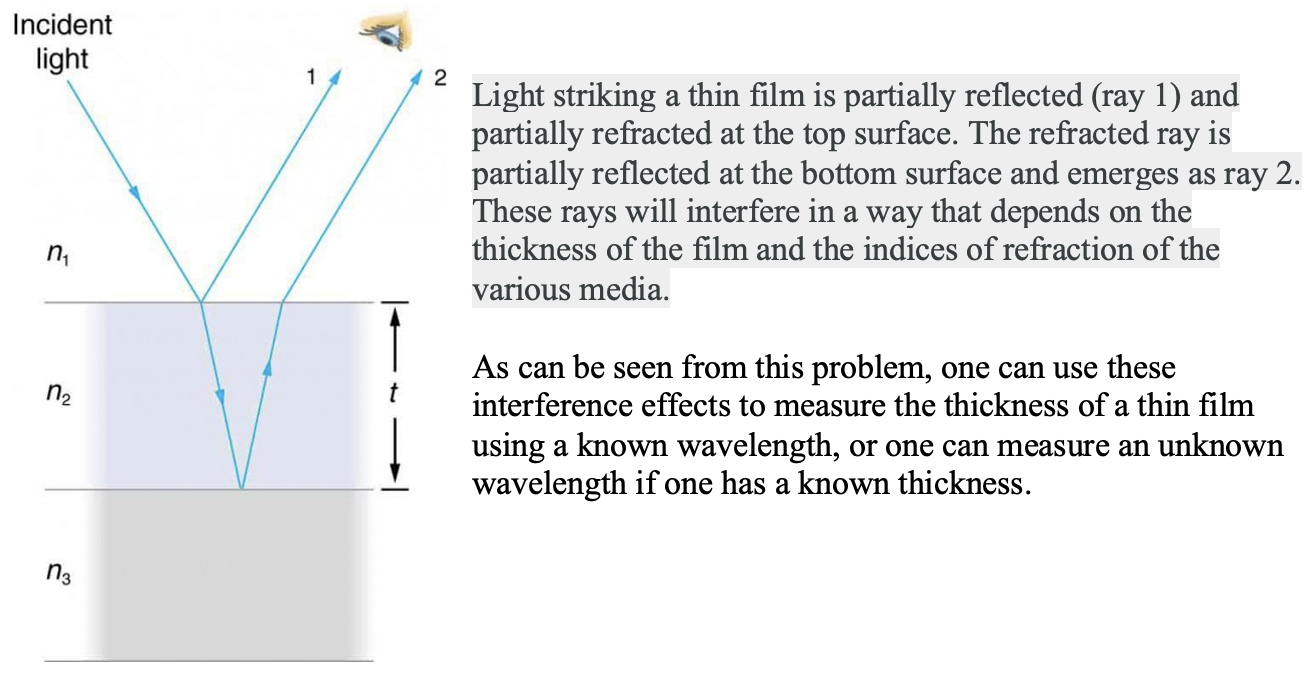
THIN FILM INTERFERENCE
The bright colors seen in an oil slick floating on water or in a sunlit soap bubble are caused by interference. The brightest colors are those that interfere constructively. This interference is between light reflected from different surfaces of a thin film; thus, the effect is known as thin film interference.

NON-REFLECTING COATING
One can coat a surface with a specific thickness of film to produce destructive interference for a particular wavelength. In that case there will be no reflection from the surface at that wavelength. This is then called a non-reflecting coating.

WEDGE
A wedgeconsistsof two smooth glass plates that make a very small angle with each other. The air between the plates forms a “thin film” whose thickness increases as we move away from the corner. For the wavelength of the incident light there will be a point along the bottom plate where the thickness of the film is just right to give constructive interference. The result is a series of “fringes,” or alternating bright and dark fringes along the glass plate.

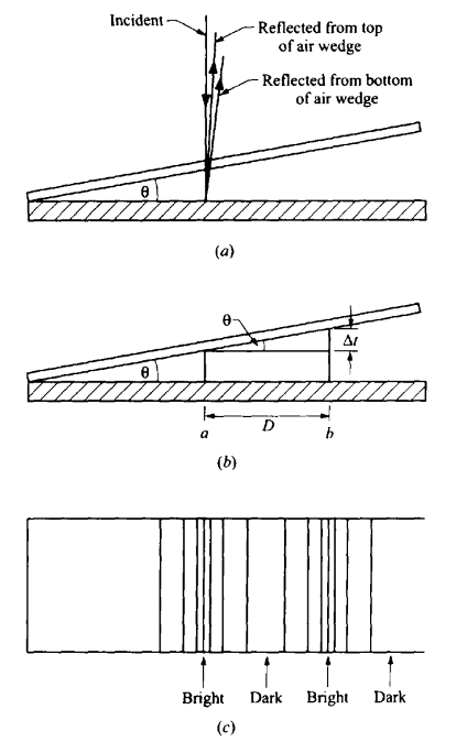
If the glass is not exactly smooth, the bright fringes will be somewhat distorted. The wavy line traces out points where the distance between the top and bottom plates is constant. This can be used to measure the smoothness of a plate. If the lines are distorted, one knows where one has to remove a small amount of glass and can grind the glass there to achieve better smoothness. Since these fringes are sensitive to distances of fractions of a wavelength, this can assure smoothness to that order of distance.

NEWTON’S RINGS
When a sector of a glass sphere is placed on a smooth glass plane, there is an air film between the lower surface of the sector and the plane. The height of this film increases as one moves out from the center. Points of equal height form circles around the center. Therefore, circular fringes appear because of the wedge principle above.

The circles seen are called Newton’s rings. This technique is used as standard procedure to test and adjust the smoothness and symmetry of spherical glass surfaces.

DIFFRACTION
Diffraction is the process by which a beam of light or other system of waves is spread out as a result of passing through a narrow aperture or across an edge, typically accompanied by interference between the wave forms produced.

SINGLE SLIT
For a single slit we get the following mathematical relationship.

w sin θ = mλ,              m = 1, 2, 3 . . . (destructive interference)

The intensities at these maxima decrease as θ increases. The intensity at the center is far greater than the intensity at any of the secondary maxima. Additionally, the central maximum is wider than any of the other maxima, and it has a width of

δcent = 2Lλ/w

The secondary fringes have width half as wide.

δ = Lλ/w

The angle of diffraction (the angle for the first minimum) increases with λ/w. The wave spreads out into a central bright fringe between (this angle). As w gets smaller, approaching λ, the central bright fringe gets bigger, and the light spreads out more widely. We therefore see that one cannot consider the light as moving in a straight line if there are apertures comparable to the wavelength of the light.
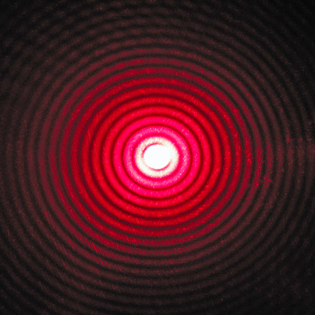
SINGLE HOLE
For a small circular aperture, the light would bend into a larger circle, with the angle of diffraction increasing as the diameter, D, of the hole decreases. The result is a bright central circular area (called the Airy disk), in which most of the energy of the light is concentrated, with secondary rings at larger angles containing smaller amounts of light energy. A small object viewed through a circular aperture expands into a larger circle, with the angle for the edge of the Airy disk given by:

sin θ = 1.22(λ/D)

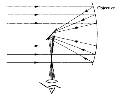
As (λ/D) becomes larger, the image size increases. If we view two neighboring tiny objects through the hole, we can no longer “resolve” them from each other. Thus, diffraction imposes a limit on our ability to resolve closely spaced objects as through telescope. For the best resolution, we must have large aperture D and/or small wavelength λ. In order to increase our resolving power we must use waves of shorter wavelength, such as ultraviolet light or X-rays, or “electron waves.” Furthermore, this is one of the reasons that telescopes are built with the largest practical diameter objective lens or mirror.

DIFFRACTION GRATING
When there are very many, closely spaced slits on a plate, we call the arrangement a “diffraction grating.” Gratings can easily have 10,000 lines per cm, giving a spacing of d = 10-6 m. The angles at which we get multiple slit maxima (the angle through which the light is “diffracted”), is given by:

d sin θ = mλ

The angle at which maxima occur clearly depends on the wavelength, and for multi-frequency light, for each value of m, there will be a spectrum of colors, from blue to red, as the angle θ increases. We can use this multiple slit arrangement to measure wavelengths very accurately, and to separate out different wavelengths in the source of light.

POLARIZATION OF LIGHT
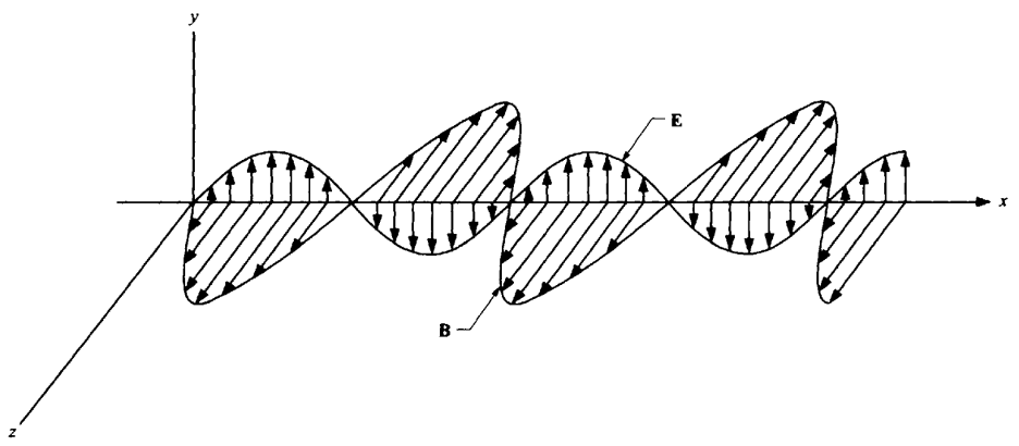
The electric field lies in the plane perpendicular to the direction of motion.  We call the direction of the electric field in this plane the direction of “polarization”. Most light that is produced by sources such as incandescent bulbs is unpolarized, meaning the electric field has no preferred direction. The simplest, and most common, case of polarization is one in which the electric field always points along one direction. This case is called linearly polarized light, or plane polarized light.

ABSORPTION (DICHROISM)
Dichroism is the property of some crystals and solutions of absorbing one of two plane-polarized components of transmitted light more strongly than the other. An example of such a material is a sheet of “polaroid”, which produces light polarized in one linear direction.

REFLECTION
Brewster’s angle is an angle of incidence at which light with a particular polarization is perfectly transmitted through a transparent dielectric surface, with no reflection. When unpolarized light is incident at this angle, the light that is reflected from the surface is therefore perfectly polarized.

BIREFRINGENCE
Birefringence is the phenomenon exhibited by certain materials in which an incident ray of light is split into two rays, called an ordinary ray and an extraordinary ray, which are plane-polarized in mutually orthogonal planes, or circular-polarized in opposite directions (left and right).

SCATTERING
Scattering offers another means of producing polarized light. In fact, the light from the sun scattered by the atmosphere (the light we see during the day if we don’t look at the sun), will be polarized, and we can selectively remove that light by using a polarizer that does not transmit that polarization.

.

Physics II: Chapter 14

Reference: Beginning Physics II

Chapter 14: MIRRORS, LENSES AND OPTICAL INSTRUMENTS

.

KEY WORD LIST

Image, Real Image, Virtual Image, Plane Mirror, Magnification, Left-Right Handedness, Concave and Convex Mirrors, Principle Axis, Focal Point, Paraxial Rays, Aberration, Extended Objects, Thin Lens, Converging Lens, Diverging Lens, Lensmaker’s Equation, Magnifying Glass, Angular Magnification, Camera, f – Number, The Eye, Myopic, Hyperopic, Reflex Action, Projector, Microscope, Telescope, Reflecting Telescopes.

.

GLOSSARY

For details on the following concepts, please consult Chapter 14.

IMAGE
When the rays of light from an object reach the eye, each of those that enter is moving in a slightly different direction. The eye has the physiological ability to trace these rays back to where they meet, and then assumes that the object is at that point of intersection. In most cases, this will give the true location of the source of light. However, if somehow the directions of the rays have been altered before they reach the eye, then the backward tracing that is done by the eye will result in an intersection of the rays at some different point, not at the actual source. This results in an “image” which is not at the position of the actual “object.”

REAL IMAGE
In the case of a real image, rays from an object have been bent to actually converge on a point in space, and then to spread out again as they pass that point until they reach the eye. In that case, the rays really come from that point, although the original source (the object) is not at that point.

VIRTUAL IMAGE
For a virtual image, the eye traces the rays back to a point through which no rays actually pass. This is the case for the source under water. Light from a source under water seems to come from an “apparent depth” which is nearer the surface than the actual source.

PLANE MIRROR
When light from a source reaches a mirror it is reflected back into the region from which it came. None of the light reaches the region behind the mirror.

The region to the left of the mirror is the “object” region since the light originates in that region. It is also the “image” region, since any real image will be formed there as a result of the reflection from the mirror into that region. If an image is formed in the region to the right of the mirror, that image would have to be a “virtual” image, since the light never actually was found in that region. We will, in fact, find that a plane mirror normally forms a virtual image.

MAGNIFICATION
We define the ratio of the image height to the object height as the magnification, defined as:

M = y’/y

where the heights are positive if they are above the base line and negative if they are below the base line. Thus, an upright image has a positive magnification, and an inverted image has a negative magnification. For the plane mirror y’ = y, and the magnification is one.

LEFT-RIGHT HANDEDNESS
In the following, the image of the child is facing the child, with the front of the head nearer the mirror than the back. We note, however, that the right hand of the child is the left hand of the image. Thus, the image has a reversed appearance concerning right and left handedness. Letters are therefore reversed and difficult to read when viewed in a mirror.

CONCAVE AND CONVEX MIRRORS
These are mirrors that are shaped to be part of the surface of a sphere of some radius R. These spherical mirrors can be “concave” if the center of the sphere is on the object side so that the inside surface of the sphere reflects light from the object, or “convex” if the center of the sphere is on the “negative” side so that the outside surface of the sphere reflects light from the object.

PRINCIPLE AXIS
The imaginary line through the center of the sphere and the center of the mirror is called the principal axis.

FOCAL POINT
Consider a series of incident rays that are parallel to the principal axis and hence to each other. We take each incoming ray and equate the angle of reflection to the angle of incidence to get the reflected ray. We note that the parallel rays closest to the principal axis have reflected rays that intersect at nearly the same point on the axis. The common point where the rays near the principal axis meet is called the focal point, and labeled F.

PARAXIAL RAYS
These are all the parallel rays near the central ray, that are reflected through nearly the same point, the focal point. For small θ, f = R/2. For a convex mirror, the paraxial rays, when reflected from the mirror, project back to a point at a distance f behind the mirror. The reverse process is also true. If rays approach the mirror at small angles to the principal axis so as to pass through the focal point (concave mirror) or to have virtual projections through the virtual focal point (convex mirror) the corresponding reflected rays are all parallel to the principal axis.

ABERRATION
If a mirror is large enough that the rays further away cannot be neglected, then the mirror will not give us the imaging properties that we want, and the mirror is said to have “aberrations”. To avoid aberrations due to these non-paraxial rays, we would need a mirror formed in the shape of a paraboloid rather than a sphere. Such mirrors are used in large telescopes.

EXTENDED OBJECTS
We can show the images of extended objects to be formed as follows. The image is real for a convex mirror, but virtual for convex mirror.

When the object is between the focal point and the concave mirror, the image formed is virtual and magnified as follows.

THIN LENS
By this we mean a thin piece of transparent material such as glass or plastic, with two spherical surfaces generally of different radii and a common principal axis. Light is incident on the lens from one side, called the object side, and is refracted at each of the two surfaces and emerges on the other side, called the image side.

CONVERGING LENS
If rays of light are incident on the lens at some angle, the converging lens will bend the transmitted light toward the principal axis. The rays coming from a point on an object and passing through the lens, converge (are focused) to a common point beyond the lens. For a converging lens, the lens is wider at the center than at the ends.

DIVERGING LENS
If rays of light are incident on the lens at some angle, the diverging lens will bend the transmitted light away from the principal axis. For a diverging lens rays from a point on the object diverge when they pass through the lens, but if we trace these rays back through the lens they appear to be coming from a common point on the object side, i.e. from a virtual image. For a diverging lens, the lens is wider at the ends than at the center.

LENSMAKER’S EQUATION
For a thin lens in air, made of material with an index of refraction n, and having radii R1 and R2:

where we assume light travels from left to right and radii are positive when light hits a convex surface and negative when light hits a concave surface. This is known as the Lensmaker’s equation.

MAGNIFYING GLASS
A magnifying glass generally consists of a converging lens, with the object (a printed page, for instance) placed closer to the lens than the focal point. A converging lens produces a larger, virtual and upright image whenever the object distance is less than the focal length. Therefore, a person looking at written material through a converging lens will see the writing behind the magnifying glass without inversion.

ANGULAR MAGNIFICATION
The magnification of magnifiers is usually expressed in terms of the “angular magnification”. If the angle subtended at the eye by the magnified image of an object is θ’, and the largest angle that the object can subtend at the naked eye and still be in focus is θ, then for small angles θ, θ’ (less than about15°) the angular magnification is expressed as θ/θ’. Angular magnification is a better measure of human perception of size increase than ordinary magnification because the size of an object, as seen by the eye, depends on the distance of the object from the eye.

CAMERA
A camera basically consists of a converging lens that forms a real image on a film placed at a certain distance from the lens. Once the focal length of the lens has been chosen, the lens will form this image only for objects at the appropriate distance from the camera. By moving the lens back and forth slightly one can arrange to focus on objects at the desired distance in front of the lens. Most good cameras have multiple lenses in order to avoid some of the aberrations due to dispersion etc.

f – NUMBER
The camera is often characterized by an “f-number”, such as f/8 (f number of 8), which is the ratio of the focal length to the diameter of the diaphragm. The f-number is a key factor in determining the proper exposure time needed to produce a good image on a given quality film.

THE EYE
The eye is very similar to a camera in the sense that a real image is formed by a lens on the retina, where nerve endings transform the light into impulses that are transmitted to the brain for analysis. The lens of the eye is attached to muscles that can stretch the lens and change the radii of its surface, thus altering the focal length. The eye automatically and rapidly changes this focal length, as needed, within its capacity to change. This capacity generally allows a healthy eye to focus on objects from a far point (nearly infinite) to a near point (about 25 cm).

MYOPIC
If the eye cannot focus on a point infinitely far away because the lens is too converging, then the eye is called myopic (nearsighted). In this case the far point has been decreased from infinity to some point nearer the eye.

HYPEROPIC
If the eye cannot focus on objects too near the eye because the lens is insufficiently converging, then the eye is called hyperopic (farsighted). In this case the near point has moved too far away, as generally happens with age.

REFLEX ACTION
The eye adjusts for different light intensities by automatically decreasing or increasing the diameter of the exposed portion of the lens. This is caused by reflex action to protect the eye from sudden changes in intensity.

PROJECTOR
The projector is the reverse of a camera. In a camera, light from a large object is focused by a lens onto a photographic plate to form a real, inverted and smaller image. In the case of a projector, light from a slide is focused onto a screen to form a real, inverted and larger image. The slide is placed upside down in the projector. Usually a powerful light source is used to shine light through the slide. The focusing, in the case of a projector, is accomplished by moving the projection lens closer to or further away from the slide.

MICROSCOPE
To increase the magnification, one can use a “compound microscope”, often called microscope for short, which consists of two or more lenses significantly separated from each other. In effect, we use a regular magnifying glass as an “eyepiece”, and a converging lens of relatively small focal length as a pre-magnifier (closer to the object) to form a larger real image that serves as the object for the eyepiece. This latter converging lens is called the “objective,” and forms an image very near the focal point of the eyepiece. The eyepiece is then used to examine this real image and form a virtual image of it near infinity, which is then viewed by the eye placed against the eyepiece. The microscope is focused by moving both the objective and the eyepiece.

TELESCOPE
A telescope is generally used for viewing objects that are very distant. Because of their distance, they appear very small to the naked eye, and subtend a small angle. In order to be able to distinguish features of the object one tries to magnify this angle so that the object will appear larger. Generally, the telescope, like the microscope, is composed of two optical elements. One is the eyepiece (also called the ocular) which is a magnifying glass. The element which first receives the light from the object is again called the objective, which forms a real image of this distant object. Since the object is distant, this image is formed at nearly the focal point of the objective. This image is then magnified by the ocular and viewed by the observer, either directly or on some recording material. Telescopes with converging lenses as objectives are called refracting telescopes.

REFLECTING TELESCOPES
In reflecting telescopes, the objective is a concave mirror, since large mirrors are more easily constructed than large solid lenses. We want a large diameter objective in order to gather lots of light to the image and to be able to see faint objects. In order to avoid problems with the need for paraxial rays, large telescopes usually employ parabolic surfaces. A small 45° flat mirror is used to allow the image to be observed by the ocular at 90° and out of the way of the incoming light.

.

Glossary of Substance

Reference: KHTK Glossary (Physics)

This is the beginning of a glossary that views SUBSTANCE in the most general manner. It is a work in progress.

.

KEY WORDS

AETHER,
COGNITIVE SUBSTANCE, CONSCIOUSNESS, CONSISTENCY,
ENERGY SUBSTANCE,
FORCE,
INERTIA, LINES OF FORCE,
MASS NUMBER, MATERIAL SUBSTANCE, MATERIALISM,
PHYSICAL, PHYSICS, PRIMARY SUBSTANCE,
SCIENCE, SPACE, SPECTRUM OF SUBSTANCE, SUBSTANCE, SYSTEM

.

AETHER
See LINES OF FORCE.

COGNITIVE SUBSTANCE
When we think, remember, or visualize, we are dealing with the cognitive substance. Our postulates, considerations, viewpoints and ideas are all made of cognitive substance. One of the intrinsic property of cognitive substance is “awareness”. This awareness can be contrasted very finely with other awareness that are present. The consistency of cognitive substance is so fine that it cannot be sensed by our physical senses. It can be sensed only by our mental sense. We may refer to the dimension of cognitive substance as “theta.” It has its own laws that are very different from the laws of physical substance.

CONSCIOUSNESS
Consciousness is the ability to sense. There is primitive consciousness only, “to evolve”, in the “primary substance.” This leads to evolution. As the substance and its form evolve, its consciousness also evolves. This consciousness is weak in inanimate objects, greater in animate organisms, and the greatest in the humankind. There is no consciousness independent of the universe. The common denominator of all consciousness is “to evolve.” The ultimate evolved consciousness is yet to be realized. It is possible that, over the millennia, many individuals may have evolved to the ultimate consciousness; but the humankind and the universe as a whole have yet to evolve to that state.

CONSISTENCY
Consistency is the degree of substantiality of substance. It is recognized as density, firmness, or viscosity of the substance. For example, “Honey has higher consistency than water.” For energy substance consistency is measured per quanta, where quanta is determined by frequency. For material substance consistency is measured by the mass of its elementary particle, such as, proton or neutron, where the elementary particle is determined by its smallest discrete inertia. The quanta and the mass of elementary particle may be measured by the same unit. Thus, substance can have a gradient of consistencies.

ENERGY SUBSTANCE
Light, radiative energy and quantum “particles” consist of energy substance. The consistency of energy substance is least for gravity and most for electrons. This consistency can be sensed and measured as momentum. Since there are no atomic particles, energy substance of same consistency may coalesce together and flow like fluids. The “quantum” does not have a center of mass to have a precise location in space. So, the concept of quanta may represent the coalesced consistency rather than the discreteness of particles. The quantum may be measured through subatomic interactions. The wave properties of wavelength and frequency are intrinsic to energy substance. Its frequency increases in parallel with consistency. 

FORCE
We perceive objects and their substance by how they impact our senses. This impact is always in the form of FORCE. Therefore, we may consider FORCE to be synonymous with substance. This was Faraday’s view. Maxwell, however, saw force only as “the tendency of a body to pass from one place to another,” which depends upon “the amount of change of tension which that passage would produce.” Thus, he saw force as change in energy over distance. Here distance is not defined but considered subjectively only. Unlike Faraday, Maxwell did not relate force directly to the nature of substance.

INERTIA
Inertia is the property of resistance to motion. We can detect something only when it resists, meaning it has inertia. The primary characteristic of substance is that it is substantial enough to be sensed or detected; or, that it has inertia. A substance always reacts to force by returning force. If there is no force returned in any shape or form, then there is no resistance, no inertia and no substance. The force defines the substance. This innate force characteristic of matter was called inertia by Newton, and he associated it with mass. But this innate force characteristic may be applied to any substance, and not just to matter. We may, therefore, associate inertia not just with mass of matter; but, with the consistency of substance. Inertia may be measured as ‘consistency’ by measuring the resistance to unit acceleration. When there is substance and inertia, there is always contact and force. So, there is feeling. 

LINES OF FORCE
Faraday conceived lines of force as the force extending between atoms that forms the fabric of space between them. These lines of force carry the vibrations of the radiative phenomena. Maxwell and other physicists postulated space consisting of mysterious aether instead.

MASS NUMBER
The mass number is the total number of protons and neutrons (together known as nucleons) in an atomic nucleus. It is approximately equal to the atomic mass of the atom expressed in atomic mass units. 

MATERIAL SUBSTANCE
We are most familiar with the material substance as matter. Its consistency is so high that it is placed in a special category called mass. The key property of material substance is the “center of mass.” This center determines the location of a material object in space. The laws of mechanics are applicable to it. The material substance comes in states of solids, liquids and gases. In solid state, the material substance can be structured into shapes that persist. Material substance of all different states may be reduced to discrete particles. The smallest particles are called molecules and atoms. The ultimate material particles are the protons and neutrons that make up the nucleus of the atom. All material particles have centers of mass. But energy “particles” do not have centers of mass and they cannot be located precisely in space.

MATERIALISM
Materialism holds matter to be the fundamental substance in nature, and all things, including mental states and consciousness, are results of material interactions.

PHYSICAL
Origin: “pertaining to nature.” Physical indicates connected with, pertaining to that which is material.

PHYSICS
Origin: “pertaining to nature.” Physics is the science that deals with matter, energy, motion, and force.

PHYSICS
The subject that addresses the energy of the external environment, and all its forms.
PHYSICS is the objective study of nature. When we say that physics is objective, we mean that there is a natural continuity, harmony and consistency among all its observations, interpretations and conclusions.
Inconsistencies among theories, lack of proper definitions, and disagreements among physicists are strong indicators of subjectivity that needs to be resolved.

PRIMARY SUBSTANCE
The primary substance is the inherent “substance-in-itself.” In Hinduism, it is symbolized as SHIVA, which is then formed into other substance through SHAKTI.

SCIENCE
Origin: “to know.” Science is systematic knowledge of the physical or material world gained through observation and experimentation.

SPACE
(1) Space is the property of extension of substance (matter, light and gravity). (2) Space is the spread of substance (mass and energy) such that it becomes really thin.

SPECTRUM OF SUBSTANCE
The gradient of increasing consistencies gives us a spectrum of substance. At the bottom we have the ephemeral thought of infinitesimal consistency. Just above it, we have the invisible energy of imperceptible consistency. At the top, we have the tangible matter of dense consistency. 

SUBSTANCE
Since the universe is substantial, it is made of substanceSubstance is anything that is substantial enough to be sensed. The root meaning of substance is: “That which stands under.” The substance may be divided broadly into: (1) cognitive, and (2) physical. The physical substance may be divided further into (a) field, (b) energy, and (c) matter. Substance has the following key properties: consistency, inertia, extents, duration, and motion. The substance that we are most familiar with is matter.

SYSTEM
Origin: “that stands together.” In physics, system refers to a physical structure considered as a whole.

.

Physics II: Chapter 13

Reference: Beginning Physics II

Chapter 13: LIGHT AND OPTICAL PHENOMENA

.

KEY WORD LIST

Physical Optics, Geometrical Optics, Refraction, Reflection, Snell’s Law, Critical Angle, Total Reflection, Angle Of Deviation, Dispersion, Rainbow.

.

GLOSSARY

For details on the following concepts, please consult Chapter 13.

PHYSICAL OPTICS
In physical optics we treat the phenomena that arise due to the wave nature of the light, as well as interference phenomena.

GEOMETRICAL OPTICS
The phenomena that arise when light can be considered to be adequately described by rays traveling in straight lines (perpendicular to the wave fronts) that change speed in moving from one medium to another. This is the case as long as the objects through which the light travels have dimensions that are much larger than the wavelength of the wave.

REFRACTION
The change of direction of a ray of light in passing obliquely from one medium into another in which its wave velocity is different. We define a quantity called the “index of refraction,” n, in terms of the velocity of light in the material, v, relative to its velocity, c, in a vacuum:

n = c/v

The frequencies of the transmitted and reflected waves are the same as that of the incident waves since the rate of oscillation in the disturbance is precisely what is propagated from one location to the next. Since T = l/f is constant we can calculate the new wavelength as the distance traveled during one period, or

λ’ = vT = vλ/c = λ/n

REFLECTION
The act of casting back the light, mirroring, or giving back or showing an image; the state of being reflected in this way. The angle of reflection equals the angle of incidence, i.e.

θr = θ1

SNELL’S LAW
The angle of refraction is given by

n1 sin θ1 = n2 sin θ2

It is important to note, as can be seen from the geometry in the figure, that the angle of incidence, reflection and refraction also represent the angles that the wave fronts of the incident, reflected and refracted waves respectively make with the surface.

CRITICAL ANGLE
When light travels from a dense (n2) to less dense (n1) medium, the angle of refraction is greater than the angle of incidence. The critical angle is defined as the angle of incidence that provides an angle of refraction of 90-degrees. 

sin θc = n1 / n2

TOTAL REFLECTION
When light is incident from a dense (n2) to less dense (n1) medium, at an angle greater than the critical angle, no light is refracted so all the light must be reflected. We call this case one of “total reflection“. Total reflection is very useful for bending light at a surface without losing any of the energy to transmission through the surface.

ANGLE OF DEVIATION
When the light leaves the prism its direction of motion is at an angle δ from the incident direction. This is the “angle of deviation“.

DISPERSION
For materials there is a small dependence of the velocity of light, and therefore n, on the wavelength. This property is called “dispersion” since it can be used to disperse the various wavelengths that are included in a beam of light into different refractive paths, creating a “spectrum”. As a result of the dispersion, white light refracted in a prism will be separated into its constituent wavelengths after passing through the prism

RAINBOW
A rainbow is another case in which the variation of index of refraction with wavelength leads to a spectrum.

.

Physics II: Chapter 12

Reference: Beginning Physics II

Chapter 12: ELECTROMAGNETIC WAVES

.

KEY WORD LIST

Displacement Current, Maxwell’s Equations, Gauss’ Law, Magnetic Fields, Faraday’s Law, Ampere’s Law, Electromagnetic Waves, Electromagnetic Spectrum, Electromagnetic Wave Equation, Energy And Momentum Flux, Poynting Vector, Radiation Pressure

.

GLOSSARY

For details on the following concepts, please consult Chapter 12.

DISPLACEMENT CURRENT
We know that the field within a parallel plate capacitor is uniform and is equal to E = q/ε0A, where q is the charge on the capacitor and A is the area of the capacitor. If the capacitor is being charged, then both q and E are changing, and we can write that ∆E/∆t = (∆q/∆t)/ε0A = ID0A, where ID is the displacement current between the capacitor plates (compared to the conductor current in the wire).

Thus,

ID = ε0A(∆E/∆t) = ε0 (∆E A/∆t) = ε0 (∆ψ/∆t)

where ψ is the electric flux through the area.

MAXWELL’S EQUATIONS
These four equations are relationships between the electric and magnetic fields and their sources, charges and currents. The electric and magnetic fluxes are determined directly from the electric and magnetic fields and are not separate variables. Thus, these equations tell us how to calculate the electric and magnetic fields that are produced by charges, both at rest and moving. The particular form that we have used for these equations is not the most useful for actual calculations but is the easiest to understand conceptually. For purposes of calculations, these equations are expressed more formally in the language of the integral and differential calculus, which can then be solved for specific cases.

(1) GAUSS’ LAW
The electric fields can be established by free charges. All electric field lines start at positive charges and end on negative charges (lines can also go to infinity, such as those of an isolated point charge, where they are presumed to land on opposite charges at that distance). By convention the number of electric field lines per unit area, the electric flux density, at a given point is chosen equal to the magnitude of the electric field at that point. It then equals the electric field at every other point as well. Gauss’ law then relates the total charge within a closed surface to the net number of electric field lines that pass through the surface.

(2) MAGNETIC FIELDS
There are no magnetic monopoles that act as sources for a magnetic field. Therefore, magnetic fields do not have poles where they begin or end. All magnetic field lines must therefore close on themselves. This means that any magnetic field line that passes through a closed surface must necessarily pass through the surface again in the opposite direction, in order to close on itself. This means that the net total magnetic flux which passes through a surface is zero.

(3) FARADAY’S LAW
An electric field can also be produced by a changing magnetic flux.

(4) AMPERE’S LAW
The magnetic fields are created by currents, either conduction current or displacement current.

These four equations constitute Maxwell’s equations, which are the fundamental laws governing the existence of electric and magnetic fields, which are jointly called electromagnetic fields. Electric fields exert forces on any electrical charges, while magnetic fields exert forces on moving charges.

ELECTROMAGNETIC WAVES
Maxwell was able to show that there were solutions to these equations that corresponded to waves propagating in free space, i.e., in regions where there are no charges or currents. These waves, which he called electromagnetic waves (EM) had special properties, which could be derived from these equations.

In the case of electromagnetic waves the time varying quantity is not the displacement but rather the electric and magnetic fields at a point in space.

These waves are transverse, and their speed, in free space is equal to

For a wave traveling in the x direction, the electric and magnetic fields associated with this wave are in the y-z plane. These fields are also perpendicular to each other, and that their magnitudes are given by:

E = cB

It is useful to consider electromagnetic waves that are sinusoidal. This means that if we take a picture of the wave at any time, the disturbance will vary sinusoidally in space along the direction of propagation. Furthermore, at any position is space, the disturbance will vary sinusoidally in time.

The disturbance associated with an electromagnetic wave is the electric and magnetic field along the wave. Light consists of electromagnetic waves in a certain frequency range to which the eye is sensitive and can “see”.

ELECTROMAGNETIC SPECTRUM
Electromagnetic waves exist with wavelengths ranging from very small to very large (and corresponding frequencies from very large to very small). The various possible wavelength (and frequency) ranges constitute the electromagnetic spectrum. For small frequencies the wave is usually denoted by its frequency, and for short wavelength it is denoted by its wavelength.

All of these waves travel with a speed of c, all are transverse, and all carry perpendicular electric and magnetic fields with them.

ELECTROMAGNETIC WAVE EQUATION
The equation for the disturbance of an electromagnetic sinusoidal plane wave, traveling in the + x direction, is given in terms of its disturbance (an electric field in the y direction) by

Here ω is the angular frequency of the wave, and k is the “wavenumber” of the wave and has units of m-1. E0 is the maximum value of the electric field and is thus the amplitude of the wave.

For spherical waves, since the area of a spherical surface is 4πr2, the intensity falls off as l/r2. The amplitude of the wave, A, is related to the intensity by I α A2, and therefore A falls off as l/r. The formula for the magnitude of E is given by

ENERGY AND MOMENTUM FLUX
The electric and magnetic fields contain energy (substance). The energy density is uE = ε0E2/2 for electric fields and uB = B2/2μ0 for magnetic fields. The electromagnetic energy of an electromagnetic wave is just the sum of the energies of its electric and magnetic fields. The maximum energy is located at those points where the fields are at their maxima, which occurs at the crests of these waves. But these crests move with time at a speed of c, and therefore the energy is transported in the direction that the wave travels at this speed. An electromagnetic wave, therefore, carries energy and momentum with it.

The average energy transported per unit area and time as the wave travels with speed c in the x direction is defined as the intensity:

POYNTING VECTOR
The Poynting vector S depicts the direction and rate of transfer of energy, that is power,due to electromagnetic fields in a region of space. Its magnitude is EB/μ0, and its direction is perpendicular to E and B, and obeying the right-hand rule.

Whenever energy moves in a certain direction, there is also a certain amount of momentum in that direction. This is because energy is substance.

RADIATION PRESSURE
One can use sunlight in space to not only supply power but to exert a force on a spacecraft. The force that is exerted on the surface can best be characterized by the force exerted per unit area, or pressure, P = F/A.

.