Reference: Beginning Physics II
Chapter 11: TIME VARYING ELECTRIC CIRCUITS
.
KEY WORD LIST
DC CIRCUIT, R-C CIRCUIT, R-L CIRCUIT, L-C CIRCUIT, AC CIRCUIT, IN PHASE, OUT OF PHASE, RMS VALUE, CAPACITIVE REACTANCE, IMPEDANCE (R-C CIRCUIT), INDUCTIVE REACTANCE, IMPEDANCE (R-L CIRCUIT), R-L-C CIRCUIT
.
GLOSSARY
For details on the following concepts, please consult Chapter 11.
DC CIRCUIT
A DC (direct current) circuit generally consists of a battery acting as the energy source, through its EMF, and causing a steady voltage to act across one or more resistors, capacitors or inductors. In the steady state, after all transient phenomena have stopped, there is no voltage across an inductor, since the current is no longer changing. There is a steady voltage across a capacitor, equal to Q/C, but there is no current flowing to or from the capacitor. The voltage across a resistor will equal V = IR.
R-C CIRCUIT
A DC circuit with a resistor R and a capacitor C shows a transient response when the switch is connected or disconnected.
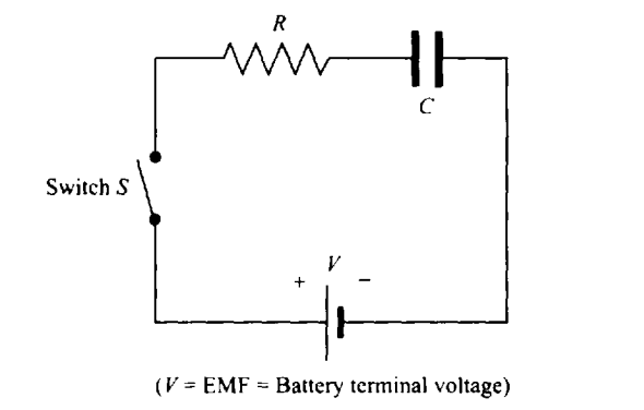
At the moment the switch is closed, there is current in the circuit but no charge on the capacitor, and when the capacitor is fully charged, there is no current in the circuit. The current decays exponentially, which can be expressed as,
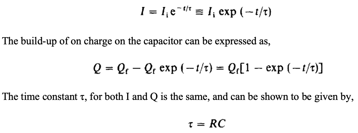
The situation is very similar in the case of the discharge of a capacitor.
R-L CIRCUIT
A DC circuit with a resistor R and an inductor L also shows a transient response when the switch is connected or disconnected.

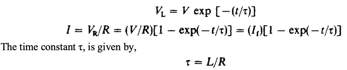
In a similar manner, if current is decreasing in an L-R circuit, it will decay exponentially with a time constant L/R.
L-C CIRCUIT
In this circuit there is no dissipation of energy because there is no resistor. The capacitor stores energy in the form of separated charges or electric fields. The inductor stores energy in the form of moving charges or magnetic fields. The total energy remains in the system.
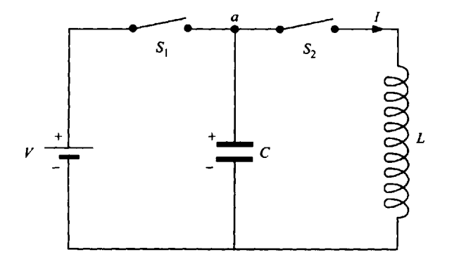
Therefore, the separated charges and the current interchange. This would be an oscillatory situation, with a repetitive interchange of energy between the capacitor and the inductor ad infinitum.

In the above circuit we first close switch S1 while S2 is open, and charge the capacitor to a voltage V, and charge Qmax. We then open S1 with the capacitor charged, and close S2 to permit the capacitor to discharge through the inductor. The capacitor discharges and then charges up again. This is similar to the case of simple harmonic motion (SHM).
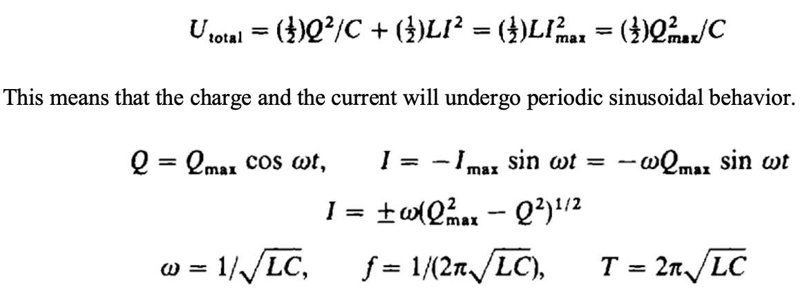
This frequency, f, is called the resonance frequency of the circuit.
AC CIRCUIT
An AC (alternate current) circuit generally consists of a source of voltage that is varying sinusoidally.In that case we expect that the variables of the circuit will also vary sinusoidally, after there has been sufficient time for the circuit to reach a steady state. This time is usually short enough that the effect of the transients can be neglected.

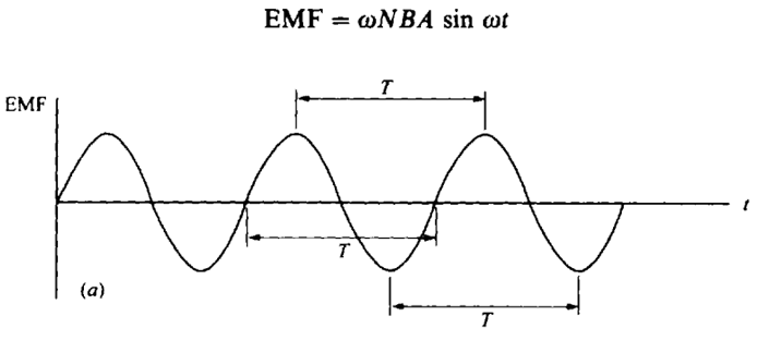
Whenever we have sinusoidal variation, we can express the variables as sine or cosine functions of time. The frequency f of the sinusoidal variation can be expressed in terms of an angular frequency ω, which simplifies the equations. Of course, the frequency can also be related to the period, T, by the relationship f= 1/T.
IN PHASE
In AC circuit with a resistor, both current i and voltage v vary identically with time as cos ωt. We say that the two are “in phase”. This means that they both attain their maximum value at the same time, and both go through zero at the same time. We will see that this is true only for a resistor, while for capacitors and inductors, the voltage will not be in phase with the current.
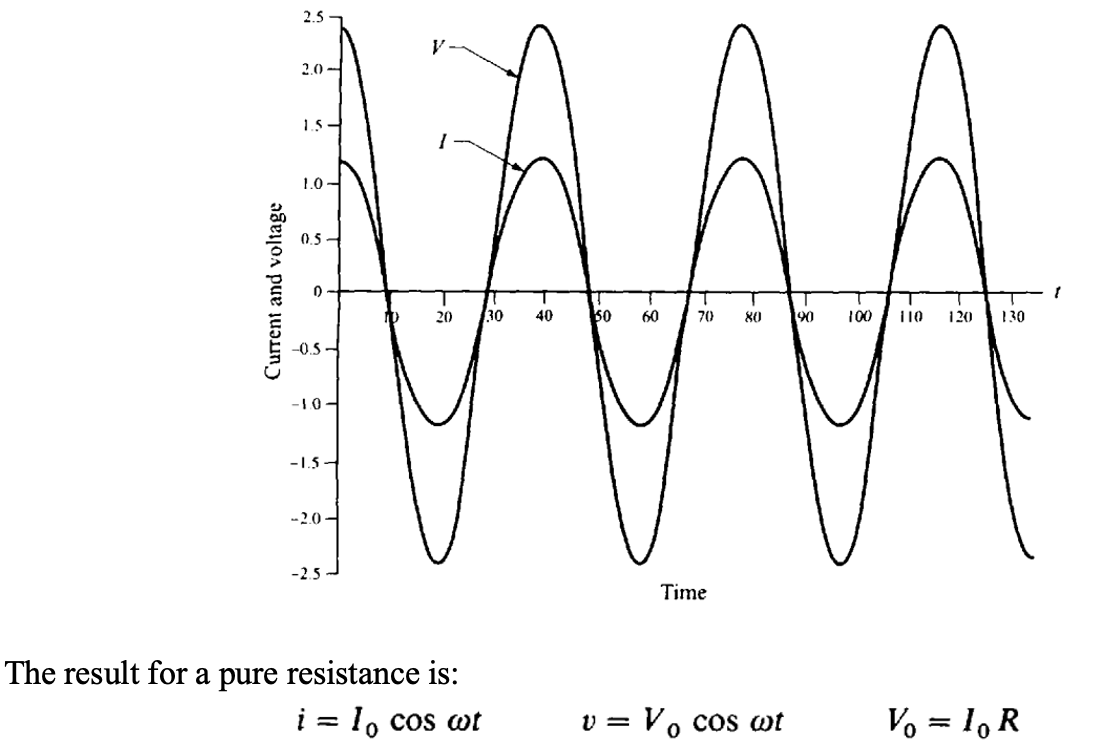
The voltage at any time is just a fixed multiple of the current.
OUT OF PHASE
When a generator causes a sinusoidal current to flow through the capacitor given by i = I0 cos ωt the capacitor is alternately charging each plate positively and negatively at a frequency: f = ω/2π. The voltage across the capacitor is defined to be from positive to negative plate and is always given as v = q/C. Both v and q will vary sinusoidally at the same frequency as the current. When the voltage reaches its peak, the current is zero. The current and voltage are said to be 90° or π/2 out of phase, and the current “leads” the voltage. We thus know that, for a capacitor, we can represent the voltage by v = VI0 sin ωt if the current is given by i = I0 cos ωt.

RMS VALUE
In most formulas used in AC circuits, the quantity we use for the “magnitude” of currents and voltages will be the RMS value, and therefore when we write just I or V we will refer to the RMS values. The term RMS actually stands for “root-mean-square”, which refers to the method used to determine its value. To get the RMS value of a variable, we have to take the square root of the average (mean) of the square of the quantity. The current will vary as i = I0 cos ωt. I0 is the amplitude of the variation, and it represents the maximum value the current can have. We have the “RMS” value: IRMS = I0 √2.
CAPACITIVE REACTANCE
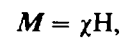
We expect that if the maximum current is increased then the maximum charge on the capacitor will increase proportionally, and therefore also the maximum voltage. Consequently, we can write that V0 = χcI0, where the constant of proportionality χc is called the capacitive reactance of the capacitor. Similarly, VRMS = χcIRMS, or V = χcI. This capacitive reactance depends on the capacitance and on the frequency. Therefore, we have,

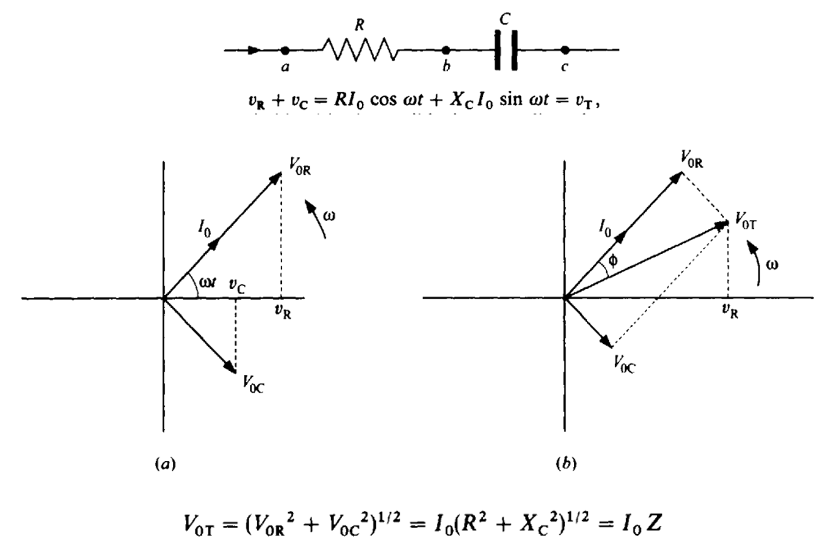
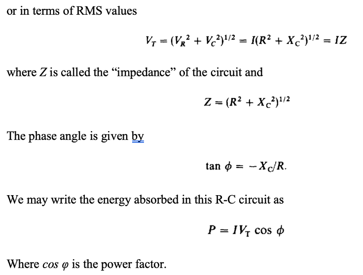
IMPEDANCE (R-C CIRCUIT)
When the Resistor and Capacitor are in Series, with the current given by as i = I0 cos ωt, the voltage across the entire circuit is
INDUCTIVE REACTANCE
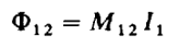
An AC generator produces a current I = I0 cos ωt in the inductor. The inductor produces a back EMF equal to (- L ∆I/∆t). This back EMF is balanced by the electrostatic voltage across the inductor, vL, as shown in the figure.
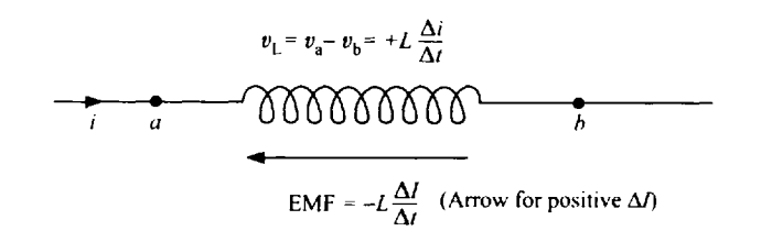
The voltage across the inductor is 90° out of phase with the current. The voltage leads the current,

IMPEDANCE (R-L CIRCUIT)
When the Resistor and are in Series, with the current given by as i = I0 cos ωt, the voltage across the entire circuit and impedance is given by

We see that cos φ is again the power factor for an R-L circuit as it was for an R-C circuit. We can generally write that cos φ = X/R, where X is the reactance of the circuit, and equals XL for a circuit with inductance and -XC for a circuit with capacitance. Similarly, the impedance can then be written as Z = (R2 + X2)1/2, which will be valid for both R-C and R-L circuits. Additionally, we can write that the total voltage will vary with time as vT = V0T cos (ω t + φ), both for the case of the R-C and the R-L circuits, For the R-C circuit, φ is negative, and in the R-L circuit, φ is positive. We will find that we can extend these ideas to the last case, the R-L-C circuit also.
R-L-C CIRCUIT
Here we have Resistor, Inductor and Capacitor in Series. We can write the equations giving these respective voltages as functions of time as:

From the phasor diagram we can deduce other relationships:

.